
China CNC Machining Factory
Milled and turned parts held to 0.01mm, from 1 piece to 50,000, quoted in 24 hours.
Send your 2D drawings and 3D CAD files for prototypes, low volume production, or repeat orders. You get a machining review, a tolerance check, and a priced quotation back on the same drawing you sent.
Before anything is cut, we go through critical dimensions, datums, material, surface finish, and inspection requirements, so you know where the machining risk sits and what has to be controlled.

Tolerance
±0.01mm
Quantity
1 to 50,000
Quote
24 h
What You Can Order Here
Everything You Need Before You Send The Drawing
Jump to the part you are checking on, from tolerances and material grades to inspection reports and what we need in an RFQ.
CNC Parts
What we machine every week
02Machining Capabilities
Milling, turning, 5 axis
03Drawing Review
DFM feedback before we cut
04Tolerances And GD&T
What we hold, and where
05Materials
Alloys, steels, plastics
06Surface Finishes
Anodizing, plating, blasting
07Prototype To Production
1 piece to 50,000
08CNC Factory
Machines and shop floor
09Inspection
First article and CMM
10Changes And Quality Control
Revisions and scrap control
11Case Studies
Parts we have shipped
12RFQ Requirements
What to send for pricing
13FAQ
Lead time, MOQ, payment
14Request A Quote
Upload drawings and specs
CNC Parts We Machine
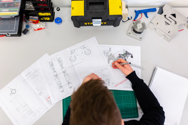
From simple turned components to complex milled housings, your parts are machined to your drawings, your material specification, and your dimensional requirements.
The examples below show the part structures, materials, and machining work we handle every week. If your part sits outside them, send the drawing or 3D model and we will review it before quoting.

Equipment Housings
Deep cavities, mounting surfaces, threaded holes, and machining from multiple sides in one controlled setup sequence.

Precision Blocks
Datum controlled surfaces, hole patterns, pockets, and the mating dimensions your assembly depends on.
Liquid Cooling Plates
Internal channels, sealing surfaces, ports, and flatness held tight enough to keep the joint leak free.

Stainless Steel Fittings
Threads, sealing surfaces, bores, and concentric features cut on one setup to protect runout.

Shafts And Bushings
Diameters, shoulders, grooves, threads, and the mating fits that decide whether the assembly slides or binds.
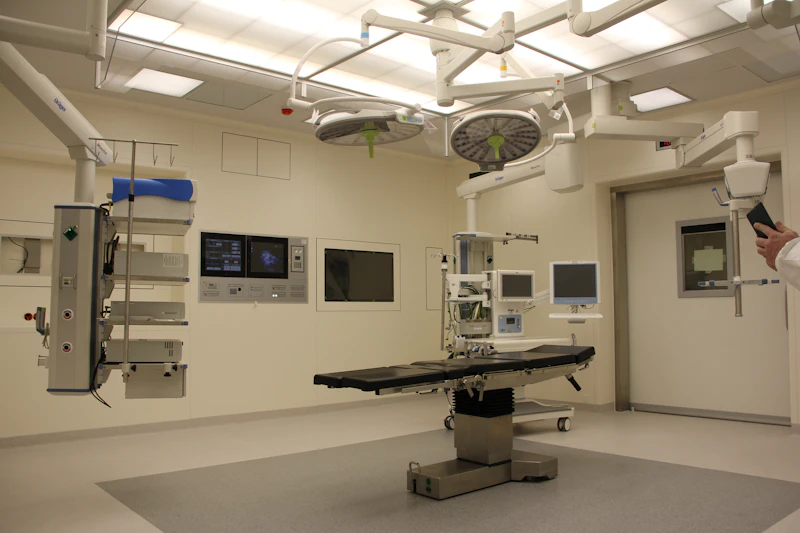
Medical Equipment Components
Multiple datum relationships, precision holes, and assembly critical surfaces inspected before the batch leaves.

Plates And Brackets
Hole positioning, pockets, countersinks, threaded features, and flat mounting surfaces that bolt down without shimming.

Complex Milled Parts
Several machining directions, complex geometry, and features that need setups planned before the first cut.
Have A Part That Is Not On The List
Send your 2D drawing or 3D CAD file and we go through the geometry, material, tolerances, and machining requirements before we put a price on it. You get the review and the quotation back within 24 hours on business days.
How Your Part Gets Cut
Different geometries need different methods, setups, and tooling strategies. The process is chosen around your part structure, tolerance requirements, material, and quantity, not around whichever machine happens to be free.


In House Machining
Core milling, turning, and multi axis work is done inside our manufacturing network, so setups, revisions, and inspection stay under one routing sheet.
External Processes
Specific grinding, EDM, heat treatment, or surface finishing runs through qualified partners. Those steps are named before quotation, so the route, the inspection points, and the acceptance condition are agreed with you up front.
Not Sure Which Process Fits Your Part
You do not need to decide the machining route before sending an RFQ. Send the 2D drawing and the 3D CAD file, and we work through the geometry, tolerances, material, and critical features first, then set the route and quote against it.
What We Check Before The First Cut
Your drawing and 3D model go through a review for anything that affects manufacturability, dimensional control, inspection, or assembly. The point is to raise the questions while they are still cheap to answer.
Critical Dimensions And Datums
Not every dimension on the print carries the same weight.
We go through critical fits, mating surfaces, hole positions, datum references, and GD&T callouts to work out which features actually drive assembly and function. If the datum structure or the acceptance condition is open to reading, we settle it with you before machining starts.


3D Model Against 2D Drawing
The model gives us geometry. It rarely carries every manufacturing requirement.
The CAD file gets compared line by line against the 2D drawing for tolerances, threads, GD&T, surface finish, and technical notes. Where the two disagree, we come back and ask which one controls, instead of picking one and hoping.
Thin Walls And Deformation
Thin wall parts move. During clamping, during material removal, and again once the fixture releases.
We look at wall thickness, unsupported areas, machining sequence, and clamping conditions to judge whether movement will push your dimensions or flatness outside what the drawing allows, and adjust the sequence before it does.

Deep Pockets And Tool Access
Deep cavities, narrow pockets, and small internal radii decide which tool can physically reach the feature.
Feature depth, opening size, internal corner radii, and tool reach get checked together. If the geometry cannot be cut reliably at that combination, we come back with the design adjustment worth discussing rather than quoting a part we will struggle to hold.
Where Tight Tolerances Belong
Tolerance belongs where the function of the part needs it, not across the whole print.
We check which features genuinely need tighter control, how they sit against the datum system, and whether the tolerance can be machined and inspected repeatably. Blanket tight tolerances add machining steps and cost without making the part work any better.


Surface Finish And Final Dimensions
Anodizing and plating add thickness. That thickness lands on your fits and mating surfaces.
Before production we confirm which dimensions are controlled after finishing, which areas need masking, what gets machined after treatment, and where final inspection happens, so the part you receive measures the way the drawing says it should.
Tolerance Follows Function, Not The Whole Print
Tightening every dimension on the drawing adds machining steps and cost without making your part work better. Each feature earns its own tolerance from what it has to do in the assembly.
Fits, mating dimensions, and critical features are reviewed one by one, so you know how each will be machined, measured, and accepted before the job releases.
| Feature | What We Review | Typical Control Approach |
|---|---|---|
| Hole Diameter | Fit, depth, and tolerance | Drilling, reaming, or boring as the fit requires |
| Shaft Diameter | Mating fit and surface requirement | CNC turning, with finishing added where needed |
| Hole Position | Datum relationship and assembly requirement | Controlled setup plus dimensional inspection |
| Flatness | Part geometry, wall thickness, and mounting function | Machining sequence plus flatness verification |
| Parallelism | Relationship between functional surfaces | Datum based machining and inspection |
| Mating Surfaces | Assembly, sealing, or contact requirement | Critical dimension and surface verification |
| Threads | Thread specification and mating component | Thread machining with gauge inspection |
Hole Diameter
What We Review
Fit, depth, and tolerance
Control Approach
Drilling, reaming, or boring as the fit requires
Shaft Diameter
What We Review
Mating fit and surface requirement
Control Approach
CNC turning, with finishing added where needed
Hole Position
What We Review
Datum relationship and assembly requirement
Control Approach
Controlled setup plus dimensional inspection
Flatness
What We Review
Part geometry, wall thickness, and mounting function
Control Approach
Machining sequence plus flatness verification
Parallelism
What We Review
Relationship between functional surfaces
Control Approach
Datum based machining and inspection
Mating Surfaces
What We Review
Assembly, sealing, or contact requirement
Control Approach
Critical dimension and surface verification
Threads
What We Review
Thread specification and mating component
Control Approach
Thread machining with gauge inspection
Fits Should Match The Function
A bearing seat, a locating hole, a sliding shaft, and a clearance hole do not need the same tolerance strategy, even when they sit on the same part.
Where your drawing specifies a fit, we look at the mating condition and what the feature has to do before choosing how it gets machined and how it gets measured.
Tight Where It Is Required
Tight tolerance on a dimension nothing depends on still costs you machining steps, inspection time, and lead time. The assembly does not get better for it.
If only certain dimensions affect fit, sealing, alignment, or function, mark those as critical on the drawing. Everything else can run at general tolerance and price accordingly.
You Hear About A Difficult Tolerance Before We Cut, Not After
When material, geometry, wall thickness, part size, or a finishing requirement makes a tolerance hard to hold batch after batch, that comes back to you during drawing review. Not once the first article has already failed inspection.
Materials We Machine
Material decides how your part cuts, how stable it stays after machining, what surface you end up with, and how it performs in service.
Metals and engineering plastics are machined to the grade, condition, and requirements written on your drawing, not to whatever bar stock is closest.

Aluminum
Housings, plates, brackets, and cooling components, wherever you need light weight without paying for difficult machining.
Confirm the alloy and temper before production. It changes strength, how the part responds to anodizing, and how much it moves after stock removal.

Stainless Steel
Fittings, shafts, and equipment components where corrosion resistance or higher mechanical strength is the reason for the material.
Grade, hardness condition, critical tolerances, and surface requirements are reviewed before machining, since stainless punishes a loose process plan.

Carbon And Alloy Steel
Hardness, heat treatment condition, and dimensional requirements all pull the machining strategy in different directions.
If your part needs heat treatment before or after machining, the sequence gets fixed before production, because it decides where the finish cuts go.

Copper And Brass
Fittings, conductive components, fluid system parts, and precision turned work where finish and concentricity matter.
Material grade, surface condition, and dimensional requirements are read against the application on your drawing before we set the process.
Engineering Plastics
Plastic parts need a different approach from metal on wall thickness, clamping force, heat generation, and how much the part moves after cutting.
Specify the exact grade when mechanical, thermal, or chemical performance is critical. Two grades of the same family will not behave the same.
Tell Us What Controls Material Acceptance
Flag anything that decides whether the material passes on your side: exact grade, alloy condition or temper, required hardness, heat treatment condition, certification, approved standard, surface treatment. A specified grade or condition never gets substituted without your confirmation.
Send certification or traceability requirements with the RFQ so they are reviewed before we quote.
Finishing Changes More Than Appearance
A coating adds thickness, and that thickness lands on your bores, threads, fits, and mating faces. It also decides corrosion behaviour and how the wear surfaces hold up in service.
Finishing requirements are read together with the drawing, so critical surfaces are settled while the part is still on the machine, not after it comes back from the finisher.
Anodizing
For aluminum parts that need corrosion resistance, wear resistance, or a controlled appearance.
Tell us the color, the anodizing type, and which surfaces have to stay free of coating before production starts.
Hard Anodizing
For aluminum components that need a harder, more wear resistant surface than standard anodizing gives.
Coating thickness moves bores, fits, and mating dimensions, so critical features are identified before machining and before finishing.
Bead Blasting
Evens out the surface and pulls back visible machining marks on suitable faces.
Define which surfaces are cosmetic and which have to stay dimensionally controlled, so blasting does not reach where it should not.
Powder Coating
For parts that need a durable coated surface in a specified color or appearance.
Threads, locating features, and mating areas usually need masking. What gets masked follows what the drawing calls functional.
Plating And Chemical Finishes
Nickel plating, zinc plating, passivation, and black oxide, depending on material and application.
Send the exact specification, the coating requirement, and the acceptance condition with the RFQ so the route is priced against the real standard.
Polishing And Surface Prep
Polishing, brushing, and other preparation for functional or cosmetic surfaces.
Clarify the surface condition you expect before production, especially where appearance, sealing, or roughness carries a requirement.
Where The Coating Stops Is A Decision, Not A Default
A bore that takes a bearing, a thread that has to run free, a face that seals against a gasket. Each one needs a call on whether coating is allowed there, and what happens to the dimension if it is.
Mark those features on the drawing and you get back the masking plan, the controlled coating areas, and any post finishing machining before the batch is released.
Rotating
Bearing and locating bores
Fits
Precision shafts and fits
Assembly
Threads
Sealing
Sealing surfaces
Electrical
Contact areas
Reference
Datum and mating faces
Agree The Accepted Condition Before The Batch Runs
Two things decide whether a finished part passes on your side: how it looks, and what it measures once the coating is on. Both are worth settling in writing.
Appearance Requirements
If the way the part looks matters, say what that means: color, gloss level, texture, which surfaces are visible in the assembly, and what cosmetic marks you can live with.
When your part has to match an existing product or an approved sample, send the reference sample or agree the visual standard before production. Matching a photo after the fact rarely ends well for either side.

Dimensions Before Or After Finishing
Where a coating moves a critical dimension, the drawing has to say whether the requirement applies before or after treatment. Otherwise two reasonable people read the same print differently.
Once that is clear, critical dimensions get inspected in the condition you actually accept, and the report you receive reflects the same condition.
A Good Sample Is Only The Start
Once a part moves from sampling into regular orders, the drawing revision, the machining method, the inspection criteria, and everything you approved have to stay controlled from one order to the next.
Prototype
The first parts exist to prove the design, the material, and the machining approach actually work together.
Find a drawing issue or a manufacturing risk here and you hear about it before anyone commits to a batch.

First Approved Batch
Once you accept the sample or the first batch, the conditions that produced it get written down instead of remembered.
That record is what the next run is built against, so the second batch is not a fresh interpretation of the same print.
Production
In batch work the job is not repeating a cycle. It is keeping the approved requirements from drifting while the cycle repeats.
Critical features are controlled against the drawing and the inspection requirements you agreed, not against a general standard.
Repeat Orders
A reorder should not start the project again from zero, and it should not cost you a new round of sampling.
If the drawing, material, or finish has changed, the new revision goes through review first. Nothing runs on an assumption that last time still applies.
When Your Volume Changes
Start with prototypes or a small batch, then scale the quantity once the part is approved. Before the volume goes up, the machining route, the fixture design, and the inspection plan get reviewed against the new quantity, because what works for 20 pieces is not always what you want running at 5,000.
Inspection Follows Your Drawing
Checks are set against your critical features and the acceptance requirements agreed for the project, at the points where a dimensional problem is still cheap to fix. Catching it at the first piece costs one part. Catching it at final costs the batch.
 01
01
Incoming Material Check
We CheckGrade, specification, and condition against what your project actually calls for, before a single cut is made.
You ConfirmCertification, hardness, or traceability requirements, settled before production starts rather than chased afterwards.
 02
02
First Piece Inspection
We CheckCritical dimensions, datum related features, fits, and anything else the drawing marks as controlled.
You GetConfirmation that the setup and the process are producing your part before the rest of the batch runs. Problems get corrected here, not counted later.
 03
03
In Process Inspection
We CheckCritical diameters and bores, hole positions, thickness, mating dimensions, flatness, and thread features while the job is still running.
Why It MattersTool wear, multiple setups, and continued stock removal all move dimensions. Frequency follows the feature, the tolerance, and the quantity.
 04
04
Final Inspection
We CheckDimensions, GD&T callouts, threads, surface condition, finishing requirements, and any acceptance criteria specific to your project.
After FinishingParts that need checking after anodizing or plating are measured in the final condition you accept, not before treatment.
 05
05
Inspection Reports
You Can GetCritical dimension records, first piece results, final dimensional reports, CMM measurements, material certificates, and surface treatment records.
Define It EarlyIf your side needs a specific report format or inspection scope, set it before production. Recreating records after shipment is rarely possible.
A New Revision Does Not Go Straight To The Floor
A revision can move dimensions, change the material, change the finish, invalidate a CNC program, and affect parts already cut. When a new drawing arrives, the change gets reviewed first, so the effective version and the parts it touches are both clear.

The new drawing is read against the revision currently in production, not opened as a fresh file.
Changed dimensions, tolerances, GD&T, materials, finishes, and technical notes are all listed before the new version is released to anyone.
The question is what the change actually reaches.
Parts made under the old revision stay distinguishable from parts made under the new one. Mixed cartons are how a revision change turns into a rejection.
If completed or in process parts are touched by the change, their status is settled before they move to the next operation.
The approved revision is written into the production documents, the CNC programs, the setup information, and the inspection criteria together, so none of them lags behind.
Where the change hits machining cost, tooling, material, or work already finished, you hear the impact before the revised requirement is released.
Production continues against the confirmed revision, and the same revision number follows the job through inspection.
That is what stops an outdated requirement from quietly coming back on the next order.
Changed Your Drawing After Ordering
Send the latest revision with a short note on what changed. That one line saves a full comparison and gets you an answer faster. We come back with which parts and which processes are affected before the revised drawing goes to production.
A Suspect Part Stops Moving
When a part misses the drawing or the agreed inspection requirement, it does not carry on down the line as though nothing happened. It gets pulled, identified, reviewed, and measured again before anyone calls it fixed.
Hold
Parts with a suspected dimensional, material, surface, or finishing issue come out of normal production and out of the shipping queue, so they never mix with accepted stock.
Identify
We pin down the affected quantity, the production stage, and the requirement that is not being met.
Review
The condition is read against your drawing and the agreed acceptance criteria.
If correcting it would touch function, geometry, or another critical requirement, it is not accepted without your confirmation.
Correct
Process adjustment, rework, re machining, re finishing, or replacement.
Which one applies follows the drawing requirement and the actual condition of the affected parts, not whichever is quickest.
Reinspect
Corrected parts are measured again against the requirements that failed, before they rejoin accepted production.
Rework being finished is not the same as the issue being resolved.
When The Issue Reaches More Than One Part
Finding a problem on one part rarely means the problem lives on one part. A worn tool, a shifted fixture, or a wrong offset affects everything that ran under the same condition.
So the affected production range gets reviewed, not only the piece where the issue surfaced. The point is knowing the full extent before the shipment leaves, instead of hearing about it from your incoming inspection.
Parts We Have Already Solved
Every part arrives with its own mix of geometry, material, tolerance, finish, and inspection requirement. These six show how the requirement was read, how the machining was planned around it, and what got verified before the parts were released.


Your part is not on this list. Send the drawing and the requirement, and you get the machining route and the inspection plan back before pricing.
What To Send For A CNC Quote
The clearer your requirements are on arrival, the closer the quote lands to the real job. These seven items cover what a machining review normally needs.
3D CAD File
Send the model whenever you have one. It carries geometry, pockets, holes, wall thickness, and tool access in a way a flat drawing cannot.
2D Drawing
This is where the requirements live that the model does not hold.
If the drawing and the model disagree, tell us which one controls.
Material
Grade and condition, not just the family. 6061 and 6061-T6 do not machine or anodize the same way.
Include hardness, heat treatment, or certification requirements with the RFQ.
Quantity
The quantity for this order, plus where the project sits overall. It changes the machining route, the fixture strategy, and how the job is planned.
Surface Finish
The finish, coating, or treatment the part needs.
Mark any threads, bores, mating surfaces, or contact areas that must stay free of coating.
Inspection Requirements
Tell us what documentation your side needs to accept the parts.
Confirm these before quotation. They shape the inspection plan and the price.
Target Schedule
Sample date, production date, or a project milestone you are working back from. The schedule gets reviewed together with material availability, machining complexity, finishing, and inspection, so what you hear back is a date we can actually hold.
Your Files Do Not Need To Be Perfect
Waiting until the drawing is finished usually costs more time than sending it early. Send what you have now.
The available 2D drawing, 3D model, or even part photos and a description are enough for a first review. You get back the list of what still needs clarifying before machining, and you can close those points while the rest of the design settles.
Send The Drawing, Get The Review First
Upload the 2D drawing and the 3D model with your quantity, material, and finish. The machining review and the quotation come back within 24 hours on business days, with anything unclear listed rather than assumed.
Send The Drawing, Get A Real Answer
Upload your 2D drawing or 3D model with the quantity, material, and finish. You get the machining review and the quotation back within 24 hours on business days, with anything unclear listed rather than assumed.

Sales Engineer
Shenzhen Worldline Technology Co.,Ltd.
Replies within 24 hoursYour message comes straight to the engineer who reviews the drawing. Send the part, the quantity, and what has to be held, and you get a machining route and a price back, not a company brochure.
A drawing that is still being finalized is fine. We machine custom parts for buyers across Europe, North America, and Southeast Asia, from single prototypes to repeat production.
Mon to Sat, 8am to 6pm China time
Tell Us About Your Part
Fields marked are required.