
China Stamping Die Components Factory
Punches, inserts, strippers and guides ground to 0.005mm and hardened to 58 to 62 HRC.
Send your drawings and we make the custom punches, die inserts, forming components, stripper components and guide components you need, whether you are building new tooling or replacing a worn part in a die that is already running.
Before anything is cut we check your critical fits, working features, material, heat treatment and drawing notes, so the part is built around the job it does in your die instead of being treated as a general machined part.
Tolerance
±0.005mm
Hardness
58 to 62 HRC
Quote
24 h
Everything You Need Before You Send The Drawing
Jump straight to what you are checking, from fits and heat treatment to how we match a replacement punch to a die that is already running.
Die Components
Punches, inserts, strippers, guides
02New And Replacement Parts
New tooling builds and spares
03Functional Requirements
What the part does in the die
04Fits And Alignment
Clearance, location, squareness
05Materials And Heat Treatment
Grades, hardness, coatings
06Manufacturing Process
Grinding, wire EDM, CNC
07Wear And Failure
Why components break down
08Replacement Components
Matching a die already running
09Inspection
Dimensional and hardness reports
10Repeat Spare Parts
Reorder from stored records
11Factory Manufacturing
Machines and shop floor
12Case Studies
Components we have shipped
13RFQ Requirements
What to send for pricing
14FAQ
Lead time, MOQ, payment
15Get Factory Quote
Drawings, quantity, hardness
Stamping Die Components We Manufacture
From single punches and inserts to guide, stripper and precision die components, every part is made to your approved drawing and to the material, hardness, tolerance and functional requirements you specify.
Building new tooling or replacing a component in a die that is already running, start with the part type you need below.

Punches
Piercing, forming and special profile punches built to your drawing, including the working profile, diameter, overall length and mounting features that have to sit right in the punch holder.
Die Inserts
Cutting, forming and replaceable inserts made to your profile, pocket dimensions and working height, so the insert drops into the die shoe and mates the way the original did.

Forming Components
Forming punches, forming inserts and profile components built around the forming geometry you need, with the radii and working surfaces finished to suit your material thickness and springback.

Stripper Components
Stripper inserts, stripper plates and related precision parts, machined with the punch clearance, guidance and mating features that keep the punch supported instead of letting it wander.

Guide And Alignment Components
Guide pins, bushings and alignment parts for the places where fit, concentricity, straightness and the sliding relationship decide whether the die stays in alignment through the run.

Die Plates And Precision Blocks
Die plates, backing components and precision blocks machined to your datums, thickness, hole locations and geometric callouts, so the stack builds up the way your assembly drawing expects.
Send The Drawing Even If The Component Is Not Standard
If your component does not fit a catalog specification, send the 2D drawing or 3D model and we review it for manufacturing before quoting. Non standard profiles, combined functions and unusual mounting arrangements are normal work here.
For a replacement part, send the original drawing together with whatever information you have on the existing component. Worn surfaces should never be treated as the original manufacturing dimensions, so we work back to the drawing intent and confirm the critical sizes with you before anything is cut.
New And Replacement Die Components
A new tooling component and a replacement part can look the same on a drawing, but what we need from you before manufacturing is very different.
We go through the available drawings, the condition of the existing part and the mating requirements before the manufacturing basis is fixed. Switch between the two below to see what each one needs.
New Die Components
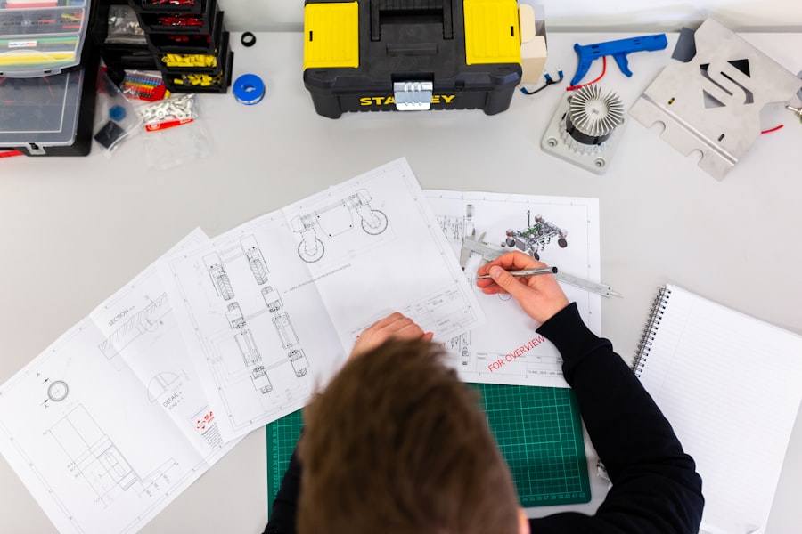
For new tooling, the approved drawing defines the component before manufacturing starts. When the drawing is complete, we build to that revision and to the requirements written on it, with no interpretation of our own added.
What The Drawing Package Should Cover

Replacement Die Components
A replacement needs one extra check, because the part in your hand may no longer carry its original dimensions. A worn cutting edge, forming surface or sliding area is never used on its own as the manufacturing reference.
What We Review Before Reproducing A Part
Do Not Copy Wear Into The New Part
If the punch on your bench measures Ø9.94mm today, that does not mean Ø9.94mm was ever its design size. Wear, regrinding, an earlier repair or edge damage all move the numbers you get off an old component.
So we check the existing part against the original drawing, the mating features and the areas that are still reliable, then agree with you on what the manufacturing reference should be before anything is cut.
Reproduce the measured size and the clearance to the die insert changes on every hit from the first stroke.
Have a replacement part to reproduce? Send the drawing, photos and whatever part information you have, and we will tell you what can safely be used as the manufacturing reference.

The Component Must Match Its Function In The Die
A die component is not defined by dimensional accuracy alone. Which features actually matter depends on what the component does, what it touches and how it works with the tooling around it.
Before manufacturing, we read your drawing around the working features, the mating relationships and how the part gets installed, then flag anything that looks inconsistent with that function.
Punches And Die Inserts
For cutting components, the punch and the die work as a matched system, so we look at both sides of that relationship rather than checking the punch on its own.
A punch can hit every dimension on its own drawing and still give you trouble if its working position or its relationship with the mating die is wrong.
Forming Components
Forming punches and inserts live or die on the geometry that produces your part shape, so that geometry gets the attention and the tighter control.
Accuracy on the forming surface usually matters more than putting the same tight tolerance on every non functional feature, which only adds cost.

Stripper Components
Stripper parts have to work around the punch while still allowing the stripping and guiding action the die was designed for.
Wrong clearance or location affects punch guidance, stripping action and wear rate even when the part measures perfectly acceptable on its own.

Guide And Alignment Components
Guide pins, bushings and related parts depend on geometric relationships far more than on any single isolated dimension.
Your drawing should say which surfaces establish the datum and which dimensions control alignment with the surrounding die structure, and we will ask if it does not.
Focus Tolerances Where They Matter
Not every feature on a die component needs the same level of precision, and pricing every dimension at the tightest callout only adds cost to the parts you order.
If your drawing marks the critical fits, working surfaces, datums and mating features, we review those separately from the general dimensions before manufacturing and tell you where the tolerance is doing real work and where it is not.
A Die Component Must Fit The Tooling Around It
A part can meet every dimension on its own drawing and still fail during assembly if its relationship with the surrounding die structure is wrong. For critical components we review fits, locating features, working positions and datum relationships together with your drawing, not as isolated dimensions.



Send The Mating Information
If you can send the mating insert dimensions, the pocket sizes or the plate hole data along with the component drawing, we can check the relationship before manufacturing instead of after your assembly finds it.
Datums Decide The Result
Where a drawing does not identify which surfaces establish the datum, we come back and ask before cutting. Guessing the reference face is the fastest way to produce a part that measures right and fits wrong.
Tell Us Which Surfaces The Part Is Built From
Datum Consistency
Critical dimensions have to be manufactured and measured from the reference surfaces you intended, not from whichever face is convenient on the machine.
When you send the 2D drawing, the 3D model and the existing part together, we check that the datum relationship still agrees across all three before production. That check matters most when the old part has already been worn, repaired or reground, because those surfaces have moved since the drawing was issued.
Define The Relationship, Not Just The Dimension
If a dimension controls a fit, an alignment, a clearance or a working position, mark it on the drawing so it reads as functional.
That one habit lets us separate the dimensions that decide whether your die runs from the ones that are simply there, and inspect the component against the features that affect assembly and press operation.
Functional Dimensions
General Dimensions
Mark the top group on your drawing and the quote comes back priced around the features that actually control the die.
Tool Steel Should Match The Application
The grade you specify for a punch, insert or forming component decides its wear resistance, toughness, edge stability and how long the part lasts in your press.
We manufacture to the grade on your approved drawing. If the material is not fixed yet, tell us what the component does and what it runs against, and we will go through the working conditions with you before a grade is chosen.
Wear Resistance
Punches and cutting inserts take repeated contact all day, and abrasive or adhesive wear slowly moves the working profile and rounds the cutting edge. What starts as a burr complaint is usually wear that has been building for weeks.
Chipping Resistance
High hardness on its own will not stop a part from failing early. Thin sections, sharp profiles, interrupted contact and concentrated local loads all need resistance to edge chipping and cracking, not just a higher HRC number on the certificate.
Toughness And Load
Some components never see uniform wear at all. They see impact, bending or a concentrated load in one spot, so the grade has to balance hardness, compressive strength and toughness instead of maximizing any one of them.
Tell Us What The Die Is Actually Running
Tool requirements shift a long way depending on what your die is processing. The same punch geometry in mild steel and in high strength steel are two different jobs, so the more you tell us about the working conditions, the better the grade and hardness recommendation you get back.
Heat Treatment Is Part Of Dimensional Control
For hardened die components, the job is not finished when the part comes off the machine. Hardness, dimensions and geometry all move during heat treatment, so the machining sequence has to be planned around the condition your critical features will finally be finished and inspected in.
 01
01
Confirm The Requirement
We CheckMaterial grade, required hardness, the heat treatment specification, which areas still need grinding or EDM afterwards, and any surface treatment or coating called out.
Production BasisWhat your drawing specifies is what we work to. If something on it conflicts with the process, you hear about it before the part is scheduled, not after.
 02
02
Plan For Heat Treatment
We DecideHow much machining allowance to leave and in what order the operations run, based on which features have to be controlled after hardening.
Why It MattersNo critical dimension should be assumed to survive heat treatment unchanged. Finishing a fit before hardening is how parts come back out of tolerance.
 03
03
Finish Critical Features
We UsePrecision grinding, wire EDM, EDM and final finishing to complete or correct the critical dimensions once the part is hardened.
Per ComponentThe route follows your actual geometry and drawing requirements. One fixed sequence applied to every die part is how thin sections crack and profiles drift.
 04
04
Verify The Final Condition
We VerifyHardness, critical dimensions, profile, flatness, parallelism, perpendicularity and fit dimensions, in the hardened and finished condition your drawing asks for.
You ReceiveInspection records matched to the approved drawing and revision, so the numbers you file can be traced back to the version you signed off.
Specify The Final Requirement On The Drawing
If hardness, treatment method or post treatment dimensions are critical to your tooling, write them on the drawing rather than leaving them to be agreed by email later. What is on the approved revision is what the part gets built and inspected against.
For a replacement component, send whatever previous hardness or material records you still have along with the existing part. Old records often explain why the last one failed early, and they keep us from repeating a specification that was already wrong for the job.
Manufacturing Built Around The Final Part
A punch, insert or forming component may pass through CNC machining, heat treatment, grinding and EDM before it is finished. The order depends on which surfaces locate the part, which features do the work, and which dimensions have to hold after hardening.
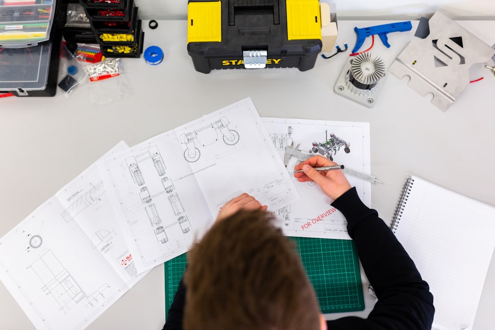
Start With The Machining Reference
Before any material is cut, we identify the datums, working surfaces and fit dimensions on your drawing. Those references decide how the part is set up through every operation that follows.
On a die insert, for example, the pocket fit and the working profile usually have to stay related to the same reference surfaces right through machining and inspection. Lose that relationship at setup two and no amount of accuracy later puts it back.
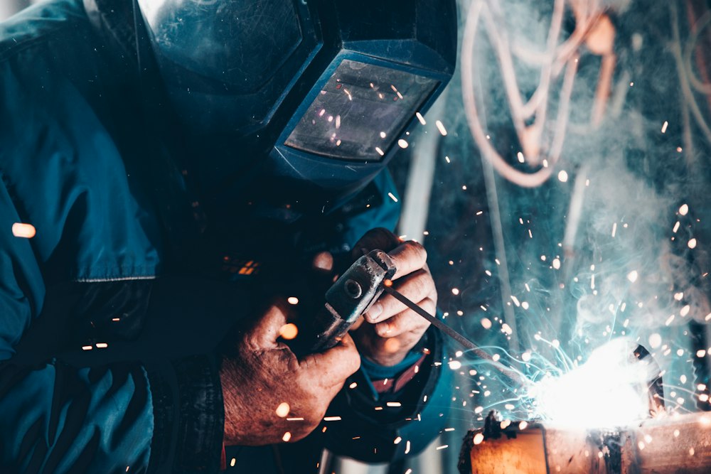
Leave Critical Features For The Right Stage
The part is rarely finished in one operation. CNC machining establishes the main geometry, holes, shoulders and locating features, and where the component will be hardened we leave material on the surfaces that still need grinding or final finishing.
The point is to arrive at the required dimensions in the condition the part will actually be used in, not in the soft condition where they are easier to hit.

Grinding Controls The Finished Relationships
After heat treatment, grinding takes over on the surfaces where thickness, flatness, parallelism, diameter or working height have to be held closely.
For punches and inserts this matters most when one finished surface sets the position of another feature inside the die. Get that face right and everything referenced from it lands where your assembly expects.

EDM Finishes The Geometry Milling Cannot
Complex punch profiles, die openings, narrow slots and internal forms go to wire EDM or EDM rather than conventional milling, and the choice comes from the geometry on your approved drawing.
On replacement parts, a worn edge or a damaged profile is never taken as the original design geometry. We work back to the drawing intent and confirm the profile with you before the wire runs.
Different Parts, Different Routes
No single process gets applied to every stamping die component. The route comes out of your part drawing, the material condition and the features that have to be correct once the tooling is assembled.
Rough Machining
Main geometry with allowance left on
Heat Treatment
Hardened to the specified range
Grinding
Diameter, shoulder and working height
Profile Finishing
Working profile and edge condition
Inspection
Verified in the hardened condition
The working diameter, profile, shoulder and overall working position are finished to your drawing requirements, in the hardened condition the punch will actually run in.
Rough Machining
Blank sized with grinding stock
Heat Treatment
Hardened before finish work
Surface Grinding
Reference faces established
Wire EDM Or EDM
Cutting or forming profile cut
Inspection
Profile checked against the fit
Pocket fit, reference surfaces and the cutting or forming profile are controlled as related features, not as three separate dimensions that happen to sit on the same part.
CNC Machining
Outline, pockets and hole pattern
Heat Treatment
Only where the drawing calls for it
Grinding
Thickness, flatness and parallelism
Precision Feature Machining
Located holes and fit bores
Inspection
Geometry checked from the datums
Flatness, thickness, hole position and the other geometric relationships decide the finishing sequence, because those are the features your whole die stack builds itself from.
Send The Drawing And We Will Tell You The Route
Once we have the part drawing, the material condition and the features that must be right in the finished tooling, you get the proposed process route back with the quote, so you know where each critical dimension is created and where it is verified.
When A Die Component Fails Too Early
A punch or insert that wears out too quickly is not always a material problem. Clearance, alignment, working geometry and the material you are stamping all push on the same result.
So when you need a replacement, the failure pattern is worth looking at before the same requirement gets manufactured a second time.
The Working Edge Wears Too Quickly
When the cutting profile slowly loses size, or the burr on your stamped part starts creeping up, the first question is not whether a harder steel exists.
The original material and hardness get checked alongside the cutting clearance, the stamped material, the working profile and where on the part the wear actually sits. If one side is noticeably more worn than the other, alignment comes into the conversation too.
What We Check First
The Edge Keeps Chipping
Repeated chipping usually means the component is seeing something other than normal abrasive wear. Very hard steel still fails if the working edge is too fragile for the geometry or the load it carries.
Clearance, edge geometry, local stress and punch to die alignment all deserve a look before another replacement goes into production, which is why changing the grade on its own is often the wrong fix.
What We Check First
The Surface Starts To Pick Up Or Score
Forming and sliding surfaces develop scoring, material pickup or galling where they keep rubbing the workpiece. Surface condition, tool material, lubrication and the material being formed all feed into it.
If you are replacing a component with visible surface damage, send photos of the damaged area and tell us where in the stroke the problem shows up. That usually points straight at which surfaces and requirements need a closer look.
What We Check First
A Failed Part Does Not Tell The Whole Story
A broken or worn component shows you where the problem happened. It does not always explain why. Press condition, die alignment, clearance, lubrication, strip material and the die design itself can all be feeding the same failure.
We use the failure information to decide which dimensional and manufacturing requirements need checking before your replacement is made, not to promise that a new part on its own will fix the whole tooling problem.
Send These With The Failed Part
Replacing A Worn Component Is Not The Same As Copying It
An existing punch or insert helps a lot when you need a replacement, but not every surface you can measure on it still represents the original design.
Wear, earlier grinding, edge damage and past repairs all move dimensions. Before we make the replacement, we separate the references that are still reliable from the areas that have to be confirmed with you.
| What You Have | What We Can Use | What Needs Attention |
|---|---|---|
| Original Drawing And Old Part | Drawing dimensions, datums and the specified material can all be checked against the component in front of us. | Any gap between the drawing and the current condition of the part gets reviewed with you before manufacturing starts. |
| Old Part Only | Mounting surfaces, locating features and unworn areas usually still give reliable references to work from. | Worn edges, forming surfaces and damaged areas are never copied straight across as design dimensions. |
| Incomplete Drawing And Old Part | Whatever the drawing does carry gets combined with the features we can still measure on the component. | Missing tolerances, original working dimensions, material and hardness may still need confirming with you. |
| Old Part And Mating Component | Fit, clearance and the working relationship can be checked far more completely with both sides in hand. | The mating relationship still has to be read against the actual condition of your tooling, not the ideal case. |
Send whichever of these you have. Even the last row on its own is enough to start a review.
Usually Reliable
Needs Confirming
What We Work Out Before Cutting A Replacement
Separate Wear From The Original Geometry
A cutting edge that has given up material, or a forming surface polished a dozen times, no longer carries the full original geometry.
Wherever possible we measure from the unworn references and check those numbers against the original drawing or the mating features, rather than trusting the surfaces that did the work.
Check The Features That Control Installation
On a replacement, outside appearance tells you almost nothing about whether the part will go in.
Pocket fit, locating surfaces, working height, shoulder position and the relationship with the mating component are what decide whether your fitter installs it in ten minutes or spends the afternoon on it.
Confirm What The Old Part Cannot Tell Us
Some information simply cannot be recovered from a worn sample. Original material grade, hardness, coating, design clearance and nominal working dimensions usually have to come from the old drawing, your tooling records or a related component.
The more original information you can send, the less we have to infer from a part that has already been in service.
Have only a worn sample?
Send photos, whatever drawings exist and a note on where the part is worn or damaged. We come back first with which features can serve as references and which ones still need confirming, before anyone talks about price.
Inspection Focused On The Features That Make The Part Work
A die component is not accepted just because its overall dimensions sit inside tolerance. Inspection concentrates on the features that decide how the part fits, aligns and works inside your die.
Your drawing and its approved revision stay the reference all the way through final inspection.
 Check 01
Profile Verification
On punches, inserts and forming components, the working profile goes back against the approved drawing rather than against the sample it was copied from.
Complex cutting contours, forming geometry and internal profiles are verified on suitable measuring equipment, so the finished shape is confirmed before anything ships.
 Check 02
Fit And Locating Dimensions
The dimensions that decide how the component installs get their own attention: punch diameters, insert outside sizes, pocket fits, locating shoulders and guide features.
These are usually the ones that determine whether your replacement drops in or needs fitting work on the bench.
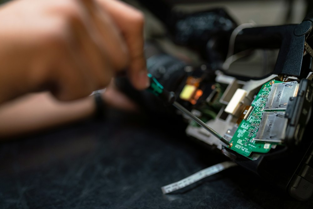 Check 03
Flatness, Parallelism And Squareness
On die plates, blocks and anything carrying reference faces, the geometric relationships matter as much as the nominal size.
Flatness, parallelism, perpendicularity and thickness are checked wherever they affect assembly position or the relationship between working features.
 Check 04
Working Height And Feature Position
Punches and inserts often depend on one specific relationship between the mounting surface and the working feature.
We check working height, shoulder position and feature location from the specified datum, not as three measurements that happen to be on the same report.
 Check 05
Hardness Verification
Where your drawing specifies hardness, it gets verified after heat treatment on the finished component.
The result is compared against the specified range for that part, not assumed from the material grade on the purchase order.
Check 06
Surface And Edge Condition
Working surfaces, cutting edges and precision fit areas are examined at final inspection under proper light.
The point is to catch damage, grinding defects, burrs and anything else that would affect assembly or the working surface once the part is in the die.
Inspection Against The Approved Revision
Final inspection runs against the drawing revision that was actually used for manufacturing. Where your project needs it, critical dimensions, profiles, hardness and other specified characteristics are recorded, so the result can be matched straight back to the drawing you supplied.
For repeat spare parts, holding the same approved revision and the same inspection requirements gives you a consistent reference every time you reorder, instead of a slightly different part each round.
Repeat Spare Parts Without Starting Over
Once a die component has been approved, your next spare should not send everyone back to square one. For repeat punches, inserts and other tooling parts we manufacture from the same confirmed production basis, as long as the specification has not changed.




Reordering something we have not made before is fine too. Send the drawing and the part reference you have, and we will tell you what still needs confirming.
Build The Spare Part Around The Approved Reference
A repeat spare should come from the approved drawing and the confirmed manufacturing requirements, not from measurements taken off a component that has already spent months working in your die. Send the earlier reference and the part gets built from the same basis as the one you signed off.
Inside Our Stamping Die Components Factory
The shop is set up for the machining, grinding, EDM, finishing and inspection of custom die components: punches, inserts, forming parts, guide components and replacement tooling.
Work is organized around approved drawings, controlled process steps and final inspection, so each component is produced against its actual functional and fit requirements rather than a generic machining spec.


Want To See How Your Component Would Be Made
Photos only show so much. If you are evaluating us as a supplier for die components, send a drawing and we will walk you through the route that part would take through the shop, which operation creates each critical feature and where it gets verified.
Buyers who want to see it in person are welcome at the factory in Shenzhen, and we can arrange a video walkthrough of the relevant machines if travel is not practical.
Die Component Projects We Have Worked On
Every die component carries a different risk. A replacement punch may live or die on its original working height, while an insert is more sensitive to pocket fit, profile or distortion through heat treatment.
These six show how the requirement was read, how manufacturing was planned around it, and what got verified before the parts shipped.

Replacement Punch
RequirementA replacement punch for a die already in production.
Key RiskThe used component was worn around the working area, so the measured worn surface could not stand in for the original manufacturing size.
What We DidThe available drawing and the unworn reference features were reviewed together before any manufacturing dimension was confirmed.
InspectionWorking profile, critical diameter, shoulder position and overall working height, all against the approved drawing.

Die Insert For Existing Tooling
RequirementA new die insert for an existing insert pocket.
Key RiskThe outside fit and the working profile both had to be controlled from the correct reference surfaces, not from each other.
What We DidThe machining and finishing sequence was arranged around the pocket fit, the datum surfaces and the final profile requirement.
InspectionInsert dimensions, profile, thickness and the relevant geometric relationships, verified before shipment.

Forming Insert
RequirementA custom forming insert built from an approved drawing.
Key RiskThe forming radius and working surface sat directly on top of the finished stamped geometry, so any drift showed up in the part.
What We DidMachining allowance and finishing operations were planned around the critical forming profile in the hardened condition.
InspectionFinished profile, radius and the specified reference dimensions, checked against the drawing.

Precision Die Plate
RequirementA die plate carrying multiple precision holes and locating features.
Key RiskIndividual dimensions were the easy part. Hole position, flatness and the datum relationships were what decided whether it assembled.
What We DidThe machining sequence was planned from the specified datum system, with final finishing applied to the critical surfaces.
InspectionThickness, flatness, hole position and the specified geometric relationships.

Repeat Spare Punches
RequirementAdditional spare punches after the previous component had already been approved.
Key RiskThe new batch had to follow the same drawing revision and functional requirements, not get rebuilt from measurements off a used part.
What We DidThe previously approved drawing, material, hardness and critical dimensions were used as the production reference.
InspectionThe same critical characteristics, checked against the same approved revision before shipment.

Complex Profile Insert
RequirementA hardened insert with a profile that conventional milling could not finish efficiently.
Key RiskThe finished profile still had to stay correctly related to the locating and reference surfaces after the profile work.
What We DidGrinding and EDM were arranged around the final profile and the datum requirements rather than run as separate jobs.
InspectionCompleted profile and critical fit dimensions, verified against the approved drawing.
Have A Similar Die Component?
Send your drawing, the existing part information or the replacement requirement. We review the component, the critical features and the manufacturing basis before anything gets quoted.
What To Send For A Quote
Send whatever you already have. A complete drawing package is the fastest route, but replacement projects can also be reviewed from the existing part plus supporting information. Tick off what you can supply and see where you stand.
Nothing selected yet
Tick the items you can supply. Even two of these are enough for us to start a review and tell you what is still missing.
The component you are holding may no longer carry its original working dimensions. Send the original drawing or the mating information along with the sample wherever you can, and we will tell you which surfaces are still usable as references.
Questions Buyers Ask Before The First Order
Most of these come up on replacement work, where the drawing is old and the part in hand has already done its time in the die. If yours is not here, send it over with the drawing.
Can you manufacture a replacement die component from a worn sample?
Yes, but the worn sample never gets treated as the original design reference on its own.
We first work out which surfaces are still reliable and which ones have been moved by wear, regrinding, damage or an earlier repair. Where you have them, the old drawing, the mating component and any tooling records get reviewed alongside the sample before replacement dimensions are confirmed.
What if the original drawing is no longer available?
An existing component still tells us a lot about geometry, locating features, fits and mounting surfaces, but some original requirements simply cannot be recovered from the part itself.
Material grade, original working dimensions, hardness, design clearance and heavily worn profiles usually need to come from tooling records, mating parts or an older drawing. We will tell you exactly which ones are missing before quoting.
How do you handle dimensions that must stay accurate after heat treatment?
The manufacturing sequence is planned around the features that have to be controlled in the finished hardened condition, not the soft one.
Depending on the component, machining allowance is left on before heat treatment, then the critical dimensions are completed by grinding, wire EDM, EDM or other finishing operations. Final inspection is carried out against the specified finished requirements.
How do you decide which dimensions are critical on a die component?
We look at what the component does rather than treating every dimension on the print the same way.
On a punch that usually means the working profile, diameter, shoulder and working height. On an insert, pocket fit and profile matter more. Guide components lean on fit, concentricity, position and alignment. Your drawing should identify these wherever it can, and we ask when it does not.
Can you match a replacement insert or punch to existing tooling?
Yes, as long as there is enough reliable information to define the relationship the part has to hold.
We review locating surfaces, fit dimensions, working height, mounting features and mating geometry. If you can send the mating component too, it often carries information that the worn replacement part can no longer show us.
How do you inspect complex punch and die insert profiles?
The method follows the geometry and the tolerance requirements shown on your drawing.
Complex profiles may go to CMM, optical measurement or another suitable method, while fit dimensions, thickness, height and geometric relationships are checked separately. The point is that the finished part is inspected around the features that control how it works inside the die.
Should I specify the tool steel and hardness on the drawing?
If your tooling design has already fixed the material and hardness, put them on the drawing and we treat them as part of the manufacturing requirement.
If they are still open, the component function, stamped material, wear condition and expected loading should be reviewed before a grade is chosen. Harder is not automatically better for every punch or insert.
Can you reproduce spare parts from a previously approved component?
Yes. Repeat spares should be built from the approved drawing revision and the confirmed production requirements, not by remeasuring a component that has already been in service.
Previous material, hardness, critical dimensions and inspection requirements stay the reference unless you have introduced a design change.
What information helps most when a punch or insert fails early?
Photos of the damaged area, plus the drawing, material, hardness and where in the die the failure showed up. Details on the stamped material, thickness, clearance, lubrication and the failure pattern all help too.
A failed component tells you where the problem happened. Wear and chipping can still be driven by alignment, tooling condition and how the press is running, so the part alone does not always identify the full cause.
Can you make one component without rebuilding the whole die?
Yes. Individual punches, inserts, forming components, guide parts and other replaceable components can be made without producing a new die, as long as the replacement requirement can be defined clearly.
What has to be established first is the correct drawing, fit, working position, material condition and mating relationships needed for the new part to work inside the tooling you already have.
Send The Drawing, Get A Real Answer
Send your 2D drawing, 3D model or the existing part information with the quantity, material and hardness. You get the manufacturing review and the quotation back within 24 hours on business days, with anything unclear listed rather than assumed.

Kim
Shenzhen Worldline Technology Co.,Ltd.
Replies within 24 hoursYour message goes straight to the person who reviews the drawing. Send the component, the quantity and what has to be held, and you get a manufacturing route and a price back, not a company brochure.
An incomplete drawing is fine, and so is a worn part with no drawing at all. We make custom die components for tool rooms and stampers across Europe, North America and Southeast Asia, from a single replacement punch to repeat spare batches.
Mon to Sat, 8am to 6pm China time
Tell Us About Your Component
Fields marked are required.